
-3 2x1.jpg)
Laser Decommissioning of Reactor Cores and Structures: U.K. Dragon and Trawsfynydd Reactors
October 8, 2025, 3:21PMRadwaste Solutions
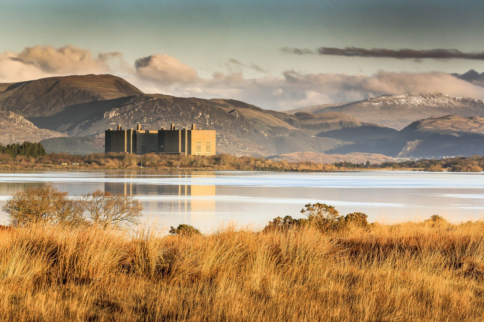
The Magnox Trawsfynydd reactor in Wales. (Photos: UK NRS)
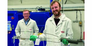
Nuclear Restoration Services (NRS), a subsidiary of the U.K. Nuclear Decommissioning Authority (NDA), has adopted laser cutting as the primary technology for the removal of the reactor core of Dragon, a 20-MWt prototype high-temperature, helium-cooled, graphite-moderated reactor at Winfrith in Dorset, England. In addition, NRS is conducting trials to establish if laser cutting will be a viable technology for the decommissioning of the Trawsfynydd reactor, a first-generation Magnox reactor (CO2 cooled, graphite moderated) situated in the Snowdonia National Park in Wales.
To continue reading, log in or create a free account!