3D Printing Possibilities: Additive Manufacturing Impact Limiters for Transportation Casks
With the significant advances in additive manufacturing (AM), otherwise known as 3D printing, Orano Federal Services and the University of North Carolina at Charlotte recently re-examined the capabilities to print impact limiters for transportation casks used to ship spent nuclear fuel. Impact limiters protect transportation casks (sometimes also referred to as transportation overpacks) and their contents during an accident. Impact limiter designs must withstand testing based on a certain significance level of hypothetical accidents, including drops, crushing, fires, and immersion in water.
Currently, many transportation casks include impact limiters made of balsawood and redwood or honeycomb aluminum structures, both of which require expensive fabrication processes (on the order of millions of dollars). Previous studies into using AM as an alternative manufacturing process for the fabrication of impact limiters identified a deficiency in the capabilities of AM printers to produce such large components, which can reach outer diameters of more than 365 centimeters (144 inches).
An updated study, however, has revealed that not only can AM printers produce substantially larger objects, but new internal patterns have been created that have the potential to provide advantages for impact limiters. In addition, some new standards have been produced to support AM (though not to nuclear standards yet), and these larger objects can be printed using metals, though still not cost-effectively for a full-scale impact limiter.
The need
Although no significant transport of commercial SNF is currently taking place in the United States to a consolidated interim storage facility or repository (there is some transport of lead test rods/assemblies of accident-tolerant fuels and higher burnup fuels, but only to facilities to be examined for operational purposes and not for storage or disposal purposes), the Department of Energy is expecting to site, license, and begin operation of a consent-based federal interim storage facility within the next 10 to 15 years [1]. As a result, the large-scale transport of commercial SNF can be expected to occur in this time frame.
In the meantime, with the recent approval of the certificate of compliance (CoC) for Orano’s high-burnup SNF demonstration cask (TN-32B) [2], and with industry’s data needs to meet commitments made to the Nuclear Regulatory Commission by 2028 for the storage of high-burnup SNF at 53 nuclear sites, the shipment of the TN-32B cask to a DOE facility for opening and detailed fuel examination is expected to occur sometime in 2027 [3].
In preparation for this potential shipment, the fabrication of all the necessary components for transport is being performed, including the fabrication of the impact limiters. Fabrication of the high-burnup SNF cask impact limiters has required the expensive purchase and interim storage of the materials needed to build them, as well as their hand assembly. As a result, alternative approaches to fabricating future impact limiters are being examined.
Alternative impact limiter designs were considered in 2019 by Orano and UNC Charlotte that included the use of alternative materials such as syntactic foams [4]. Experience from this activity provided the basis for performing this latest investigation, which included the following design and regulatory criteria:
A maximum dimensional constraint of 128 in. in width (Plate E train car dimensional limit).
A maximum composite transportation cask system weight of less than 360,000 pounds.
Temperature limits between -20°F and 150°F.
The impact limiter must remain attached to its cask after a drop.
Free drop: 9-meter (30-foot) drop onto an unyielding surface.
Crush: a crushing impact from a plate weighing 1,100 lbs. dropped from 30 ft onto the cask.
Puncture: a 3-ft drop onto a 6-in. diameter mild steel vertical cylinder.
Thermal: a fully engulfing flame of 1,475°F for 30 minutes.
Immersion: a submersion of 50 ft into water.
The last five items above are tied to hypothetical accident conditions (HAC) that are identified in 10 CFR Part 71.73 and posed the largest challenge in the designing of impact limiters at the time. This previous experience included examining some AM options. At that time, however, the technology was too limited to produce the “qualified” components needed to assemble impact limiters, as metal printing was relatively new.
AM status
An investigation of the status of available commercial metal printers found that no printer is currently capable of producing an entire impact limiter (too large). However, two promising technologies capable of printing larger metal components that could be assembled into an impact limiter were identified: fused filament fabrication (FFF) and selective laser melting (SLM) printers.
The larger commercial SLM printers available (e.g., the NXG 6II 600) can print objects as large as 600 millimeters × 600 mm × 600 mm (23.6 in. × 23.6 in. × 23.6 in.) with high precision and at a rate of 1,000 cubic cm per hour (61 in.3/hr) using a stainless steel powder. The larger commercial FFF printers available (e.g., EBAM 300) can print objects as large as 5,791 mm × 1,219 mm × 1,219 mm (228 in. × 48 in. × 48 in.) at a print rate of 1,170 cm3/hr (71.4 in.3/hr) also using a stainless steel powder, but with less precision than the SLM printers.
In addition to these stainless steel outer dimensions, these printers can also print various infill patterns such as Schwartz-D, Schwartz-P, gyroid, and honeycomb (see Fig. 1), some of which are inspired by wood microcell structure.
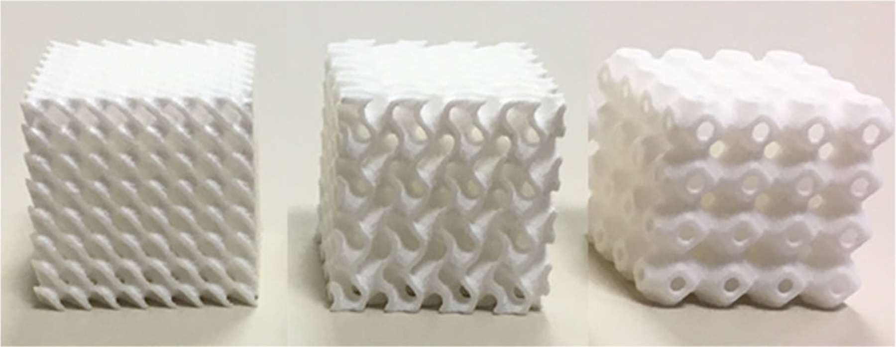
Fig. 1. Example AM infill designs: Schwartz-D (left), gyroid (center), and Schwartz-P (right) [5].
A structural assessment of these infill patterns established the gyroid as the most promising to be applied to impact limiter components, as it can have up to an 80 percent weight savings (depending on the density of the infill), it has strength in all directions, and it is less dense than other infills. The ability of these printers to print these patterns in stainless steel at various densities is a significant development, as the infill pattern density can be optimized to provide the necessary energy absorption of the impact limiter to protect the transportation package while at the same time reducing the material necessary to fabricate the impact limiter, saving on both cost and weight.
Although AM equipment has advanced, there are still some deficiencies associated with this technology. Currently, there is a lack of standards, specifically nuclear-grade standards, associated with the fabrication of AM components to ensure the efficacy of such equipment to perform safety functions. There are general standards such as ISO/ASTM 52900, “Additive Manufacturing—General Principles and Terminology,” but they just provide general information. There are efforts, however, underway to provide techniques to improve the inspection of AM equipment, which are typically verified through computed tomography [6].
Another deficiency with the current commercial AM printers is that they are not able to print full-scale impact limiters. Therefore, the impact limiters designed by Orano and USC are made up of multiple AM printed components and assembled into full-scale impact limiters.
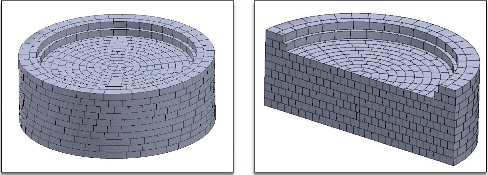
Fig. 2. The initial 2,700-brick impact limiter design.
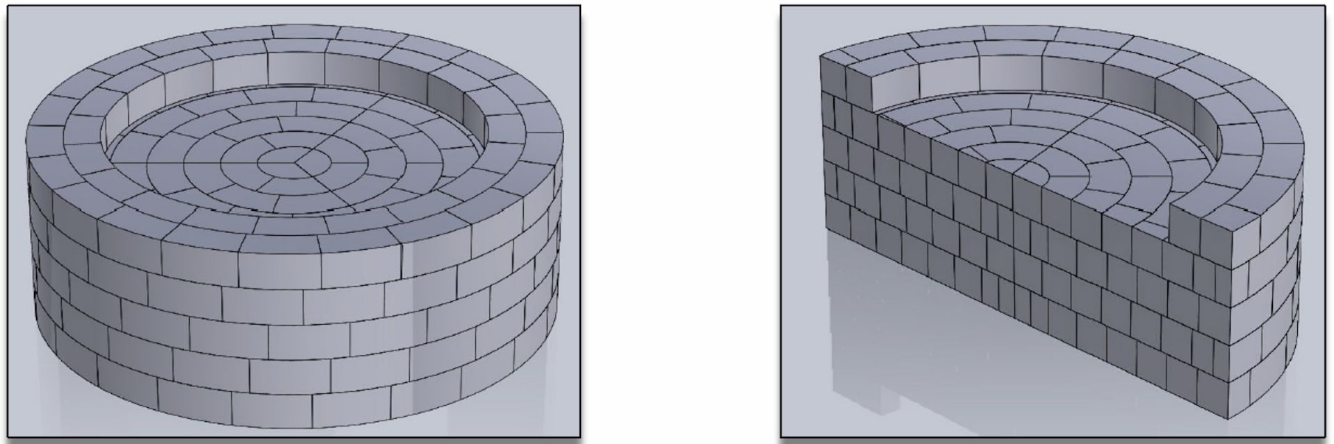
Fig. 3. The upgraded 442-brick impact limiter design using an SLM AM printer.
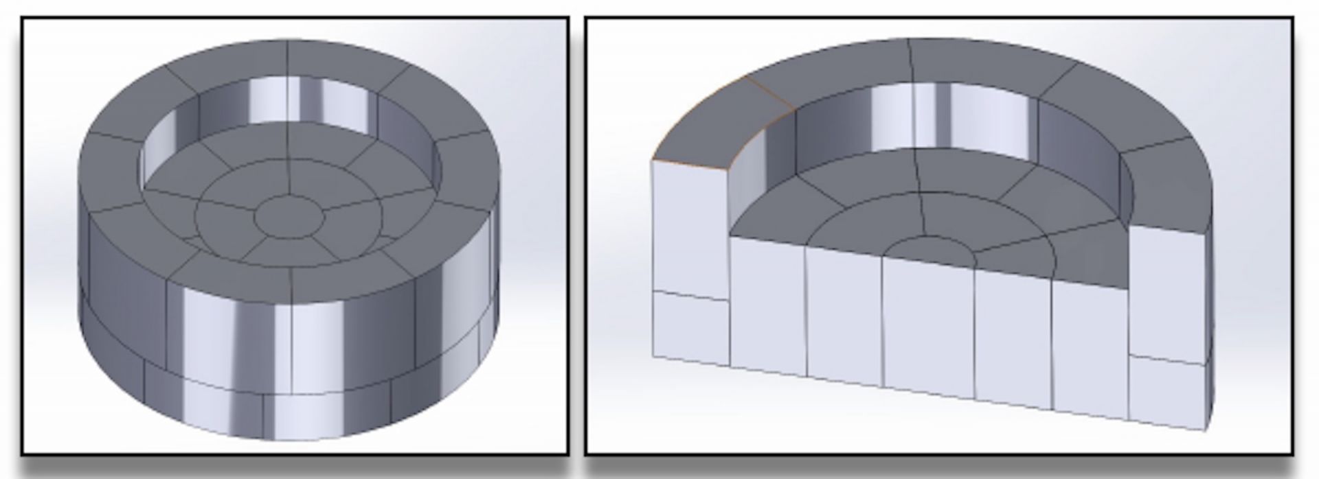
Fig. 4. The final 36-brick impact limiter design using an FFF AM printer.
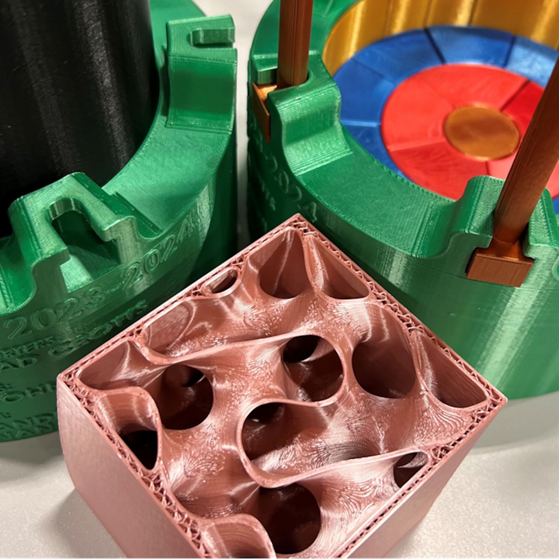
Fig. 5. AM PLA plastic scaled replica of an impact limiter (1/12 scale) with 36 bricks (red, blue, and gold) and stainless steel cladding (green) and gyroid infill pattern in foreground (pink).
Design advancements
As a result of AM only being able to print components (“bricks”) for an impact limiter, some initial designs were considered that could take advantage of the size of the AM bricks produced by the various AM printers. The first design considered bricks sized about 5 in. × 5 in. × 10 in. that aligned with the maximum size produced by a commercially available AM printer, but which required 2,700 bricks to produce a full-scale impact limiter (see Fig. 2). With the advent of larger commercially available SLM AM printers, a larger AM-fabricated brick (10 in. × 10 in. × 20 in.) was considered that would use 442 bricks to reach full-scale (see Fig. 3).
For both designs, however, although the bricks are relatively simple to print, the assembly of all the bricks into an impact limiter design within an aluminum cover was considered challenging. In addition, it was thought that the horizontal shear planes may not perform well for corner drops.
Fortunately, FFF AM printers continued to increase in size and an alternative impact limiter design was created using 20-in. × 20-in. × 40-in. bricks in a 36-brick arrangement (Fig. 4). As a result of this design, horizontal slip planes were avoided and the assembly of the impact limiter is relatively simple, especially compared to the other two designs.
The resulting design of an optimally designed AM impact limiter uses 36 bricks assembled and placed within stainless steel cladding with the bricks printed using an FFF printer. Figure 5 is a picture of a scaled mockup of this impact limiter that has been AM printed out of plastic to show the different components that make up this design, including the stainless steel cladding (green), and the four types of bricks (yellow, blue, red, and gold at center) built from the outside in. In addition, an example of the gyroid infill pattern found inside the bricks is shown in the foreground (pink) in the figure.
Analyses and testing
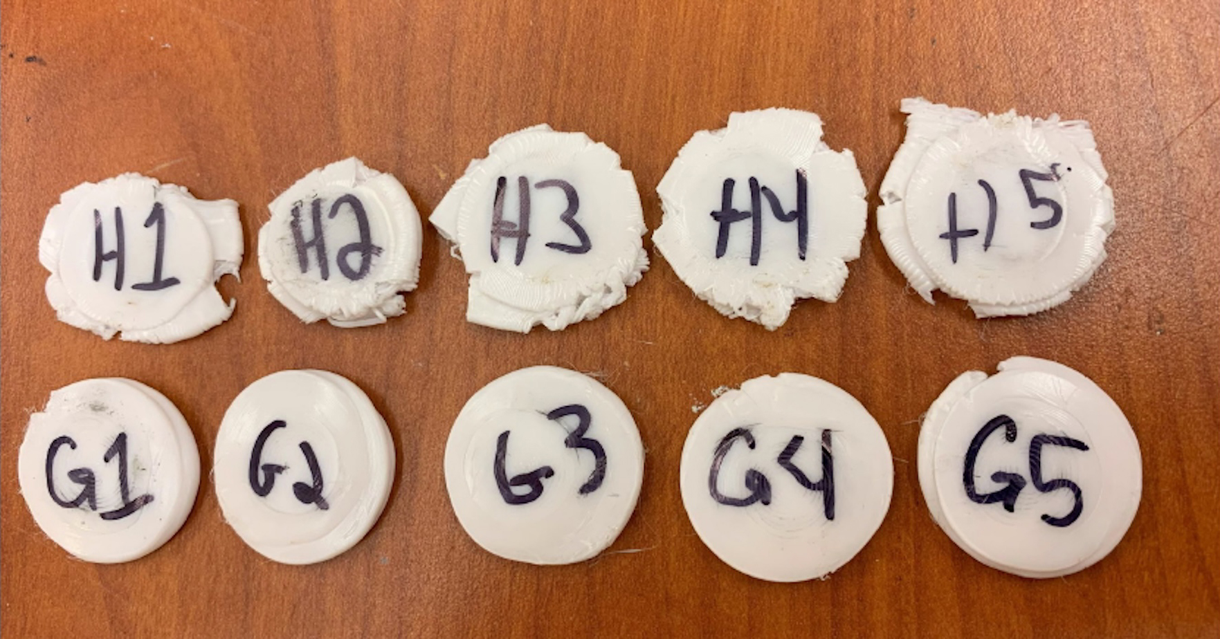
Fig. 6. Compression results for gyroid (bottom) and honeycomb (top) samples.
To examine the way honeycomb and gyroid infill patterns withstand impacts, compression tests were performed on small AM samples of the patterns (see Fig. 6). The results consistently showed better performance of the gyroid design over the honeycomb for compressive stresses and impact energy absorption, as shown in Fig. 7, with the honeycomb infill pattern outwardly collapsing and the gyroid infill pattern inwardly collapsing (i.e., accordion crushing). Hence, using a honeycomb infill pattern could either cause bricks to be forced out of the overall impact limiter design or cause distortion within the impact limiter structure (bubbling up) and potentially create uneven impact forces/stresses to select bricks in an impact. On the other hand, if a gyroid infill pattern brick were subject to an impact, then the brick would accordion crush as it absorbs the energy.
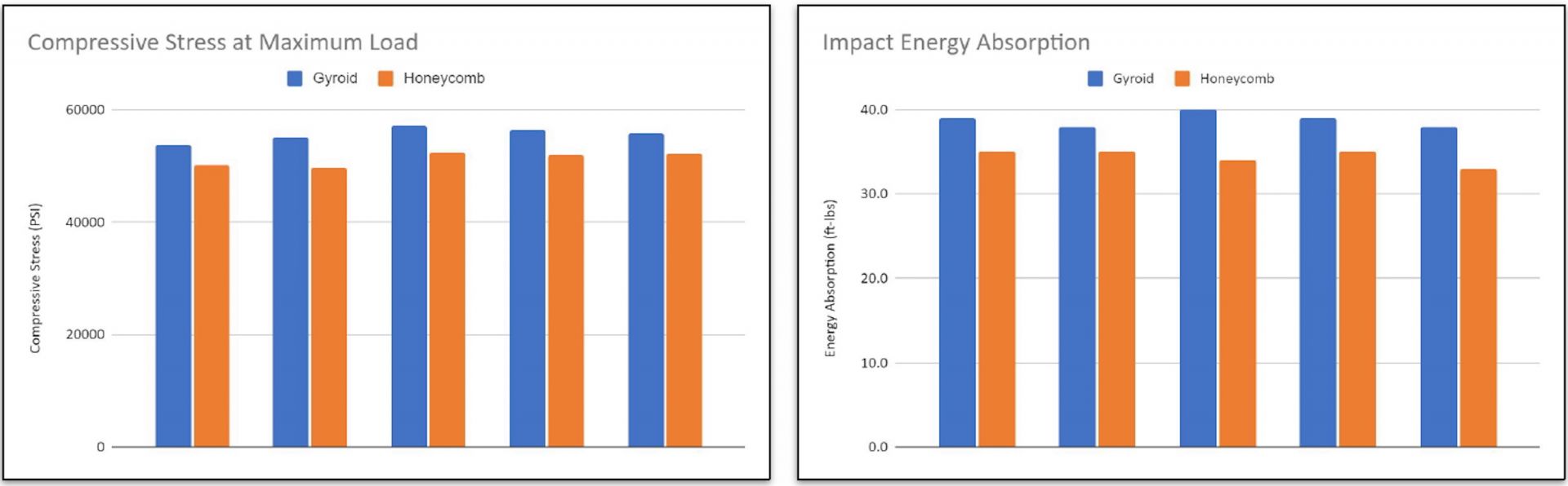
Fig. 7. Compressive stresses at maximum load (left) and impact energy absorption (right) for gyroid (blue) and honeycomb (orange) samples.
AM also provides the opportunity to change the density of the infill patterns from 0 percent (no infill) to 100 percent (solid infill). So compressive tests were also performed on samples of polylactic acid (PLA) plastic and 17/4 precipitation-hardened stainless steel (17/4 PH SS)—a commonly used metal in AM printers—containing four different infill percentages of the gyroid infill pattern: 5 percent, 10 percent, 20 percent, and 30 percent. Figures 8 and 9 illustrate the compressive stresses and the energy absorbed, respectively for the PLA plastic and stainless steel from these tests. In general, the greater the infill density, the greater the compressive stress and energy absorbed, with most of the increases uniform except for a significant increase in the energy absorbed for the stainless steel, 30 percent infilled gyroid over the other infill densities.
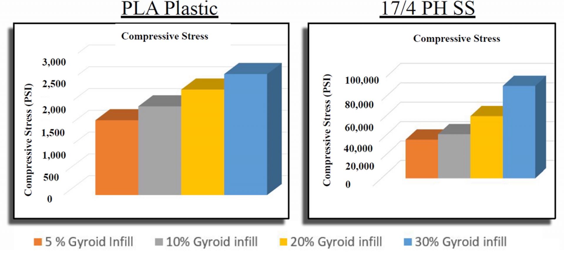
Fig. 8. Compressive stresses for PLA plastic and 17/4 PH SS for gyroid infills of different densities.
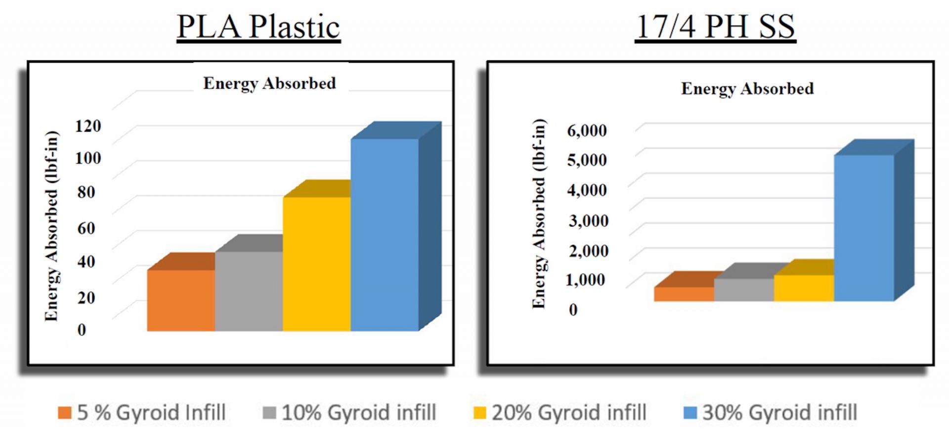
Fig. 9. Energy absorbed for PLA plastic and 17/4 PH SS for gyroid infills of different densities.
In addition to the compression tests, a model of an impact limiter assembly was constructed using SolidWorks and then analyzed using ANSYS simulations. The model was designed to allow for different materials to infill the impact limiter, with the current model considering redwood and 442 100 percent infilled bricks of 17/4 PH SS.
The resulting maximum deformations for a compression test were 0.00553 in. for the redwood and 0.00139 in. for the stainless steel. To reduce the infill in the bricks to a value less than 100 percent, Ntopology was used to turn the complex geometry associated with the gyroid infill pattern into a representative volume element (RVE) with equal properties (e.g., Young’s Modulus, Bulk Modulus, Shear Modulus) for use in the simulation model. As a result, ANSYS simulations were then produced for different drop scenarios, including side and corner drops with 5 percent and roughly 10 percent infill densities. The resulting modeled stresses on the impact limiters were acceptable for all the drop scenarios, and the 5 percent gyroid infill density produced a maximum stress (68 kilos per square inch) approximately equivalent to redwood (67 ksi) for the 30-ft drop scenario.
As a result of these tests and simulations, the 36-brick impact limiter design is considered acceptable, with each of the bricks designed with a 5 percent to 30 percent gyroid infill pattern using AM FFF printers.
Cost assessment
One of the main drivers for examining the AM fabrication of impact limiters is to reduce costs, which for currently certified impact limiters is significant due to materials (e.g., redwood) and assembly costs. Some initial cost estimates have been identified as approximately between $250,000 and $1 million per impact limiter. The cost estimate for AM components of an impact limiter is primarily associated with the cost of the printer itself, which ranges between $600,000 and $1.5 million, and the materials used by the printer, which cost approximately $50 per pound per spool of 17/4 PS SS for FFF printers and approximately $14 per pound of powder 17/4 PS SS for SLM printers. This assessment assumed the cost of labor to be $50 per hour.
The AM cost assessment considered the 36-brick impact limiter design for FFF printers and the 442-brick impact limiter design for SLM printers. The assessment established the approximate cost breakeven point between redwood impact limiters and the SLM and FFF impact limiter designs based on the percentage of gyroid infill. Assuming the redwood impact limiters cost approximately $1 million per unit, then the breakeven cost occurs for an infill of 37 percent for the SLM AM impact limiter and an infill of 10 percent for the FFF AM impact limiter. Infills at lower percentages result in cheaper AM impact limiter designs.
Since a 5 percent gyroid infill was assessed to produce acceptable results for drop events through the numerical models, impact limiters produced by FFF AM components could save over $1 million, and a set produced by SLM AM components could save over $1.7 million at this infill.
Conclusions
Compression testing and ANSYS modeling has provided some insights into the performance of the updated AM components and the new impact limiter design, including behavior comparable to current designs. Furthermore, with the ability to not only produce unique infill patterns, such as the gyroid, but also to change the density of this infill, optimization of the impact limiter design for cost and for the ability to protect the transport package against hypothetical accidents can be performed. The gyroid infill pattern with a density of 5 percent appears to meet these requirements while also minimizing the cost, with a potential savings of $1 million over the existing impact limiter design.
However, the lack of codes and standards to support the use and verify the efficacy of AM components makes the proposed new impact limiter design an exercise in need of justification, likely beyond single component testing and numerical modeling of the composite design and most likely in need of actual drop testing data. Therefore, although this work shows the promise of AM, the path forward is focused on the development of codes and standards for AM components, which will require test data to complete.
Sven Bader is a technical executive at the Electric Power Research Institute; Brad Crotts is a principal engineer at Orano; Michael Smith is an assistant professor of mechanical engineering technology at UNC Charlotte; and Don McGee and John McEntire are project managers at Orano.
References
- U.S. Department of Energy, “Consent-Based Siting Process for Federal Consolidated Interim Storage of Spent Nuclear Fuel,” (April 2023).
- U.S. Nuclear Regulatory Commission, “Certificate of Compliance No. 9377, Revision No. 0, for the Model No. TN-32B Package,” ML21231A189, (July 1, 2024).
- True, Douglas, senior vice president and chief nuclear officer of Nuclear Energy Institute, letter to Kathryn Huff, assistant secretary, Office of Nuclear Energy, subject “The High Burnup Used Nuclear Fuel Demonstration Cask Project,” (March 15, 2024).
- Bader, S., and M. Smith, “Alternative Impact Limiter Designs for Used/Spent Nuclear Fuel Transportation Casks” (19496), 2019 Waste Management Conference, Phoenix, AZ, (March 3-7, 2019).
- Castro, A., et al., “Permeability versus Design in TPMS Scaffolds,” Materials, DOI:10.3390/ma12081313, (2019).
- DOE Office of Nuclear Energy, “New National Lab Algorithm Enables Faster, Safer Inspection of Nuclear Materials,” (Nov. 1, 2024).